74hc595 Lcd Driver
Arduino 8.8 Led Matrix Driver With 2. 74HC595 Shift Registers: I bought a 8x8 Led Matrix including a driver board with a MAX7219CNG chip. Unfortunately this chip was not working properly. So I decided to build my own driver with the help of 2 74HC595 shift registers.My solution is based on the 'Multiplexing w. A portable rotary phone with ePaper display Posted 2 days ago; Adafruit MLX90640 IR Thermal Camera Posted 3 days ago; The ZT-2020 is a portable SunVox synth Posted 4 days ago; This joystick-controlled machine draws light trails using a laser Posted 5 days ago; Carve 2.5D shapes out of foam with this Arduino-controlled hot wire cutter Posted 1 week ago.
When I put it on, it forces the audio to my headphones and all other sounds outside the DAW youtube for example come from my speakers.Can you explain Asio4All to a complete beginner? Asio 4 typhoon drivers for mac pro.
Shift1 System for 1-wire Shift Registerswww.RomanBlack.comShift1 system for 1-wire shift registersUsing a shift register to get 7 or 8 output pins from 1 PIC pin!- 3rd Nov 2009.What is it?My Shift1 System is a cheap and simple way to get lots of digitaloutput pins and only needs 1 PIC pin to drive it.You can often buy CMOS Shift Register ICs very cheap, and this can bea great way to get more output pins from your PIC. But to drive a shiftregister generally needs 2 or 3 control pins. My system on this pageonly needs ONE PIC pin!I should state that I did not invent the idea of controlling ashift register with one RC network! This is an old idea I have seenmany years ago.
IntroductionHD44780 based character LCDs require at least 6 I/O lines from microcontroller to display data. Therefore, they are not suitable for low-pin microcontrollers like PIC12F series microchips.
In this project, I am going to show how to drive an HD44780 based LCD display with only 3 pins of a microcontroller. I am going to demonstrate it with PIC12F683 microchip. The character data and command from the microcontroller is transferred serially to a shift register (74HC595), and the parallel output from the shift register is fed to LCD pins. About 74HC59574HC595 is a high-speed 8-bit serial in, serial or parallel-out shift register with a storage register and 3-state outputs.The shift register and storage registers have separate clocks, SHCP and STCP respectively. Data in the shift register is shifted on the positive-going transitions of SHCP, and the content of shift register will be transferred to the storage register on a positive-going transition of the STCP.
If we tie both the clocks together, the shift register will always be one clock ahead of the storage register. The 8-bit data of the storage register will appear at the parallel output (Q0-Q7) when the output enable (OE) is low.In this project, SHCP and STCP are tied together. So, if we want to receive a serially transferred 8-bit into parallel form at Q0-Q7, an extra clock pulse is required after transmitting the 8-th bit of serial data because the clocks are tied and the storage register is 1-clock behind the shift register. HD44780-based character LCDAll HD44780 based character LCD displays are connected using 14 wires: 8 data lines (D0-D7), 3 control lines (RS, E, R/W), and three power lines (Vdd, Vss, Vee). Some LCDs may have LED backlight and so they may have additional connections (usually two: LED+ and LED-).Rajendra Bhatt4723Photo4IntroductionHD44780 based character LCDs require at least 6 I/O lines from microcontroller to display data.
Therefore, they are not suitable for low-pin microcontrollers like PIC12F series microchips. In this project, I am going to show how to drive an HD44780 based LCD display with only 3 pins of a microcontroller. I am going to demonstrate it with PIC12F683 microchip.
The character data and command from the microcontroller is transferred serially to a shift register (74HC595), and the parallel output from the shift register is fed to LCD pins.About 74HC595. 74HC595 is a high-speed 8-bit serial in, serial or parallel-out shift register with a storage register and 3-state outputs.Pinout1The shift register and storage registers have separate clocks, SHCP and STCP respectively.
Data in the shift register is shifted on the positive-going transitions of SHCP, and the content of shift register will be transferred to the storage register on a positive-going transition of the STCP. If we tie both the clocks together, the shift register will always be one clock ahead of the storage register.
The 8-bit data of the storage register will appear at the parallel output (Q0-Q7) when the output enable (OE) is low.In this project, SHCP and STCP are tied together. So, if we want to receive a serially transferred 8-bit into parallel form at Q0-Q7, an extra clock pulse is required after transmitting the 8-th bit of serial data because the clocks are tied and the storage register is 1-clock behind the shift register.HD44780-based character LCDAll HD44780 based character LCD displays are connected using 14 wires: 8 data lines (D0-D7), 3 control lines (RS, E, R/W), and three power lines (Vdd, Vss, Vee).
Some LCDs may have LED backlight and so they may have additional connections (usually two: LED+ and LED-).Pinout2Providing detail explanation of individual LCD pin doesn’t fall within the scope of this project. If you are a beginner with LCD, I recommend to read these two articles first from Everyday Practical Electronics magazine: How to use intelligent LCDsPart 1: 2.

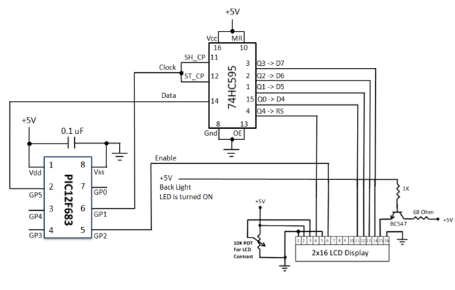
The hardware part of this project is fairly simple. The challenging part is to write the driver software that is responsible for a proper sequence of operations required to serially transfer character data and command to 74HC595 serial-in parallel-out shift register. The shift register parallel output is then connected to LCD data lines (D4-D7) and RS control pin. This arrangement requires 3-pins of microcontroller to display character data on a parallel LCD display: 2 pins for providing Clock and Data to 74HC595, and 1 pin for enable control (E) pin of LCD module. Since the data transfer uses 4-bit mode, any 8-bit command or character data is sent in two steps: send the higher nibble first, and then the lower nibble.
The R/W control pin is grounded, and therefore no data or status read from the LCD module is possible in this case.The SHCP (11) and STCP (12) clock inputs of 75HC595 are tied together, and will be driven by one microcontroller pin. Serial data from microcontroller is fed to the shift register through DS (14) pin. OE (13) pin is grounded and reset pin MR (10) is pulled high. Parallel outputs Q0-Q3 from 74HC595 are connected to D4-D7 pins of the LCD module. Similarly, Q4 output serves for RS control pin.
If the LCD module comes with a built-in backlight LED, it can simply be turned ON or OFF through LED control pin shown above. Pulling the LED pin to logic high will turn the back light ON.
SoftwareA first, a bit of data fed to DS pin of 74HC595 appears at Q0 output after 2 clocks (because SHCP and STCP are tied). So, sending 4-bit data (D4-D7) and an RS signal require 6 clock pulses till they appear at Q0-Q4 outputs respectively. When the LCD module is turned ON, it is initialized in 8-bit mode. A number of initializing commands should be sent to operate the LCD module in 4-bit mode. All the driver routines that are discussed here are written in mikroC compiler.
They work only for a 16×2 LCD module. User can modify the initialization operations inside the InitializeLCD routine to account for other LCD configurations. The driver routines and their functions are described below.– InitializeLCD: It initializes the LCD module to operate into 4-bit mode, 2 lines display, 5×7 size character, display ON, and no cursor.– WriteLCDData: Sends a character byte to display at current cursor position.– WriteLCDCmd: Write a command byte to the LCD module. – WriteLCDNibble: Data or command byte is sent to the LCD module as two nibbles. So this function routine takes care for sending the nibble data to the LCD module.– WriteLCDText: This routine is for sending a character string to display at current cursor position.– PositionLCD: To change the current cursor positionAt the beginning of your program, you need to define DataPin, ClkPin, and EnablePin to the chosen microcontroller ports. I am going to demonstrate here how to use these driver routines to display two blinking character strings, Message1 and Message2, at different locations. I am going to test our serial LCD module with PIC12F683 microcontroller.
The test circuit is shown below.Note: My PIC12F683 SettingsRunning at 4 MHz internal clock, MCLR disabled, WDT OFF.Clock, Data, and Enable lines are served through GP1, GP5, and GP2 ports.For more detail.